
Clinical Pearl
9 (
182-189
3
); 182-189
doi:
10.25259/APOS_78_2019
Clinical guidelines to integrate temporary anchorage devices for bone-borne orthodontic appliances in the digital workflow
1Private Orthodontic Practice, Smile AG, Belp, Bern, Switzerland,
2Department of Orthodontics, European University College, Dubai, UAE

First Author: Dr. Simon Graf.
*Corresponding author: Ismaeel Hansa, Department of Orthodontics, European University College, Building 27, 3rd Floor, DHCC, Dubai, UAE. drismaeelhansa@gmail.com Published: 2019-09-28,
Accepted: 2019-08-26,
Received: 2019-06-16
How to cite this article: Graf S, Hansa I. Clinical guidelines to integrate temporary anchorage devices for bone-borne orthodontic appliances in the digital workflow. APOS Trends Orthod 2019;9(3):182-9.
Accepted: 2019-08-26,
Received: 2019-06-16
© 2019 Published by Scientific Scholar on behalf of APOS Trends in Orthodontics
Licence
This is an open-access article distributed under the terms of the Creative Commons Attribution-Non Commercial-Share Alike 4.0 License, which allows others to remix, tweak, and build upon the work non-commercially, as long as the author is credited and the new creations are licensed under the identical terms.
This is an open-access article distributed under the terms of the Creative Commons Attribution-Non Commercial-Share Alike 4.0 License, which allows others to remix, tweak, and build upon the work non-commercially, as long as the author is credited and the new creations are licensed under the identical terms.
How to cite this article: Graf S, Hansa I. Clinical guidelines to integrate temporary anchorage devices for bone-borne orthodontic appliances in the digital workflow. APOS Trends Orthod 2019;9(3):182-9.
Abstract
In this article, we demonstrate different approaches to enhance the integration of temporary anchorage devices in the digital workflow of the daily orthodontic practice. We describe methods of varying complexity which could be used depending on the equipment available in the orthodontic clinic.
Keywords
Digital workflow
Technology
Temporary anchorage devices
Three-dimensional orthodontics
INTRODUCTION
Over the past two decades, temporary anchorage devices (TADs) have become a vital part of orthodontic treatment, revolutionizing treatment possibilities in adults[1,2] and adolescents,[3,4] as well as in non-compliant patients.[5,6] During the same period, the exponential development of digital technology has also drastically influenced the practice of orthodontics.[7-10] However, the integration of TADs into the digital workflow has yet been rudimentary. Thus, guidelines are needed to help orthodontists integrate TADs in the modern orthodontic clinic.Although few orthodontists have fully embraced a digital workflow and many do not have the latest equipment, clinicians may opt to integrate bone-borne appliances into their clinical repertoire. Some clinicians may possess cone-beam computed tomography (CBCT) machines and/or intraoral scanners, while others may utilize only conventional radiography and impressions. Hence, we aim to describe different ways to integrate TADs and bone-borne appliances in the digital workflow, depending on the available equipment.
CONVENTIONAL APPROACH
If only conventional radiographs and impressions (alginate or silicone) are available, the TADs are first placed in the ideal location within the T-Zone described by Ludwig et al.[11] and an impression is made with (or without) impression caps. Thereafter, the impression is either scanned directly or the cast is poured and scanned indirectly, using a desktop scanner or a CBCT machine at an orthodontic laboratory. The resulting three-dimensional (3D) file (e.g. STL file) then needs to be inspected to determine if the TAD head is clearly distinguishable. If not completely distinguishable, the TAD head on the 3D image needs to be replaced using a digital implant analog to provide clear borders of the implant head [Figures 1-4]. A superimposition in the 3D space requires three clearly defined spots to overlay an object. If an impression cap was used, the cap first needs to be removed digitally. The easiest way to perform the superimposition is with a two-piece, or two-step, digital implant analog, provided by the implant company. The first step is to place and superimpose the digital implant analog with the cap over the scanned implant head, then with a single click, the impression cap is removed or replaced with the implant analog without the cap. Subsequently, the STL file with the clearly defined TAD head can be printed and used to fabricate a TAD-supported device using the conventional device or can be used for a virtual design and print of the appliance.[12,13]
Close
Figure 1::
Digital temporary anchorage devices superimposition. Adding the digital analog (with an expansion screw inserted for virtual appliance design).
Digital temporary anchorage devices superimposition. Adding the digital analog (with an expansion screw inserted for virtual appliance design).

Close
Figure 2::
Digital temporary anchorage devices superimposition final position reached (with an expansion screw inserted for virtual appliance design).
Digital temporary anchorage devices superimposition final position reached (with an expansion screw inserted for virtual appliance design).

Close
Figure 3::
Digital temporary anchorage devices superimposition final position (with an expansion screw inserted for virtual appliance design).
Digital temporary anchorage devices superimposition final position (with an expansion screw inserted for virtual appliance design).

Close
Figure 4::
Digital temporary anchorage devices superimposition final position three-dimensional check with different transparencies (with an expansion screw).
Digital temporary anchorage devices superimposition final position three-dimensional check with different transparencies (with an expansion screw).
INTRAORAL SCAN
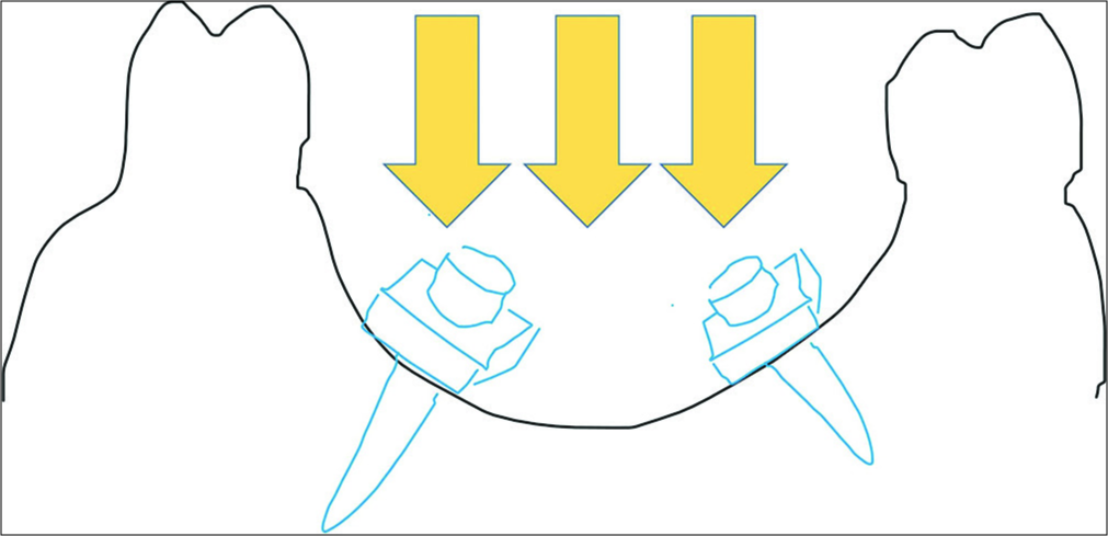
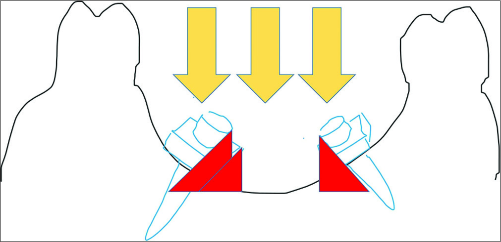
If an intraoral scanner is available, the TAD head can be readily scanned. Some scanners are incapable of capturing metal structures, therefore, for these scanners, powder (according to the scanner instructions) or occlusion spray (3M, used for prosthodontic occlusion check) is required.[13]There are some fundamental concepts to consider when scanning the implant head. An intraoral scanner (specifically the software) relies on a continuous surface. Consequently, if the implant shoulder is too wide and the light beam of the scanner cannot pass beneath it [Figures 5 and 6], the software will delete the implant head as it is identified as an artifact. There must be a connection from the palatal surface to the implant head for the head to be recognized as “real” by the software and not be deleted. To reduce this risk, it is the best to insert the TAD until the shoulder has a solid contact with the palatal mucosa. If this is not possible, orthodontic wax can be gently adapted around the implant neck (being careful not to cover the coupling part of the TAD) to provide a good continuous surface for the scanner to capture accurately. Depending on the shape and contour of the palate, it is not always possible to scan the entire implant head [Figure 7] as the light beam cannot pass beneath the implant head. In these cases, a digital implant analog (described as before) [Figure 8] is mandatory to provide a distinct TAD head for the production of an appliance. If the position of the TAD does not allow a proper scan, a scan body may help. A scan body is similar to an impression cap and is produced from a material that is easily captured by the scanner. Different TAD companies provide different designs for scan bodies (e.g., PSM Medical Solutions, Tuttlingen, Germany) [Figures 9-12]. The STL files then need to be processed with the digital implant analog as described previously in the classical approach.
Close
Figure 5::
Scan beam during temporary anchorage devices scan.
Scan beam during temporary anchorage devices scan.
Close
Figure 6::
Scan beam during temporary anchorage devices (TADs) scan demonstrating undercuts and shadow of the TAD shoulder.
Scan beam during temporary anchorage devices (TADs) scan demonstrating undercuts and shadow of the TAD shoulder.

Close
Figure 7::
Incomplete intraoral scan of the temporary anchorage devices.
Incomplete intraoral scan of the temporary anchorage devices.

Close
Figure 8::
Temporary anchorage devices scan intraoral with digital analog superimposition.
Temporary anchorage devices scan intraoral with digital analog superimposition.

Close
Figure 9::
Occlusion with temporary anchorage devices in situ without scan bodies.
Occlusion with temporary anchorage devices in situ without scan bodies.

Close
Figure 10::
Occlusion with temporary anchorage devices in situ with scan bodies.
Occlusion with temporary anchorage devices in situ with scan bodies.

Close
Figure 11::
Occlusion scan with temporary anchorage devices in situ with scan bodies.
Occlusion scan with temporary anchorage devices in situ with scan bodies.

Close
Figure 12::
Digital cast with PSM scan body maxi.
Digital cast with PSM scan body maxi.
CEPHALOMETRIC RADIOGRAPHY AND INTRAORAL SCAN
If an intraoral scan and cephalometric radiograph are available, these can be used for a virtual setup with palatal TADs. A digital cast generated from a conventional alginate impression could be used as well.Onyxceph software (Image instruments, Chemnitz, Germany) allows for merging of the 3D cast with a cephalometric radiograph by superimposition over the incisors. This allows for planning of the position of the TADs in the palate based on the bone thickness seen on the cephalometric radiograph [Figures 13-16]. The TADs, available in a library, are positioned using the software at the appropriate location for the appliance. It is then possible to print the cast and produce the appliance with a surgical splint to guide the TAD placement. The appliance can be fabricated conventionally on the printed cast or can be designed digitally and printed directly. The same protocol can be used for fabricating the surgical splint with the appropriate drill guide. With this protocol, it is possible to insert the TADs and fit the orthodontic appliance in one session, thus reducing chair time and number of appointments for the patient and orthodontist.

Close
Figure 13::
Temporary anchorage devices match by Onyxceph.
Temporary anchorage devices match by Onyxceph.

Close
Figure 14::
Matching the intraoral scan with the Ceph.
Matching the intraoral scan with the Ceph.

Close
Figure 15::
Check of the temporary anchorage devices position in relation to bone availability.
Check of the temporary anchorage devices position in relation to bone availability.

Close
Figure 16::
Matching the temporary anchorage devices with the combined scan and Ceph.
Matching the temporary anchorage devices with the combined scan and Ceph.
CBCT AND INTRAORAL SCAN
The ideal clinical setup for a digital workflow is with a CBCT machine and an intraoral scanner. With this setup, it is possible to plan the position of the TADs entirely in 3D. The intraoral scan is superimposed on the CBCT and the ideal TAD and appliance location are planned. If the appliance is fitted to the implant head and tooth surface only (and not the mucosa), it is possible to skip the intraoral scan completely, as the surface of the tooth can be clearly discerned by the CBCT. The appliance can then be designed digitally and a tooth-supported surgical splint can be printed. If there is any contact of the appliance on the palatal mucosa, it is vital to utilize and superimpose the intraoral scan over the CBCT to avoid fitting problems during insertion in the mouth. Another method of fabrication of the appliance and surgical splint is on the 3D-printed cast with the planned TADs inserted. If the orthodontic clinic is not equipped with a laboratory, it is possible to outsource that step (e.g., Easy Driver system, Union Tech Lab, Italy) [Figures 17-21]. The Onyxceph software (Image instruments, Chemnitz, Germany) also offers the processing and merging of the CBCT and the intraoral scan [Figures 22 and 23].
Close
Figure 17::
Easydriver match of the scan and cone-beam computed tomography (Homepage Uniontech).
Easydriver match of the scan and cone-beam computed tomography (Homepage Uniontech).

Close
Figure 19::
Temporary anchorage devices positioning splint offered by Easydriver, Uniontech (Homepage Uniontech).
Temporary anchorage devices positioning splint offered by Easydriver, Uniontech (Homepage Uniontech).

Close
Figure 18::
Check of the temporary anchorage devices position with the Easydriver system (Homepage Uniontech).
Check of the temporary anchorage devices position with the Easydriver system (Homepage Uniontech).

Close
Figure 20::
Temporary anchorage devices in situ with the Easydriver splint (Homepage Uniontech).
Temporary anchorage devices in situ with the Easydriver splint (Homepage Uniontech).

Close
Figure 21::
Benefit system inserted in the same appointment with the temporary anchorage devices, due to the Easydriver system (Homepage Uniontech).
Benefit system inserted in the same appointment with the temporary anchorage devices, due to the Easydriver system (Homepage Uniontech).

Close
Figure 22::
Planning of the temporary anchorage devices with Onyxceph on an intraoral scan (with hypothetic roots) and cone-beam computed tomography.
Planning of the temporary anchorage devices with Onyxceph on an intraoral scan (with hypothetic roots) and cone-beam computed tomography.

Close
Figure 23::
Position check of the temporary anchorage devices with Onyxceph on an intraoral scan (with hypothetic roots) and cone-beam computed tomography.
Position check of the temporary anchorage devices with Onyxceph on an intraoral scan (with hypothetic roots) and cone-beam computed tomography.
DISCUSSION
The more technology advances for intraoral scanning and virtual planning software, the easier the combination of TADs and other preformed parts will become for our orthodontic treatment. We are standing on the edge of a paradigm shift in orthodontics, transitioning from analog orthodontics to digital orthodontics, and every clinician has to ask themselves if and when they will be ready to make the jump.[10,14,15] However, in the private clinical setting, this decision must also be financially viable. Based on this, it may be easier to adapt slowly by initially outsourcing certain steps, until cost and efficiency allow for complete in- house fabrication. The scope of 3D and digital technologies is not only limited to TADs or bone-borne appliances but also includes 3D-printed removable appliances,[16] indirect bonding,[8] clear aligners,[16-18] customized appliances,[19-23] and for retention.[16,24]CONCLUSION
To remain at the forefront of advancement in the field of orthodontics, every clinician should consider when is the right time to fully commit to the digital era. Embracing new technology, sooner rather than later, will hopefully push the orthodontic specialty to new heights by allowing us to expand our boundaries in efficiency and effectiveness and improve orthodontic care.Financial support and sponsorship
Nil.Conflicts of interest
There are no conflicts of interest.References
- Costa A, Raffainl M, Melsen B. Miniscrews as orthodontic anchorage: A preliminary report. Int J Adult Orthodon Orthognath Surg. 1998;13:201-9
[Google Scholar]
- Luzi C, Verna C, Melsen B. Guidelines for success in placement of orthodontic mini-implants. J Clin Orthod. 2009;43:39-44
[Google Scholar]
- Ngan P, Moon W. Evolution of class III treatment in orthodontics. Am J Orthod Dentofacial Orthop. 2015;148:22-36
[CrossRef] [PubMed] [Google Scholar]
- Wilmes B, Vasudavan S, Drescher D. Maxillary molar mesialization with the use of palatal mini-implants for direct anchorage in an adolescent patient. Am J Orthod Dentofacial Orthop. 2019;155:725-32
[CrossRef] [PubMed] [Google Scholar]
- Wilmes B, Nienkemper M, Ludwig B, Kau CH, Pauls A, Drescher D, et al. Esthetic class II treatment with the beneslider and aligners. J Clin Orthod. 2012;46:390-8
[Google Scholar]
- Ravera S, Castroflorio T, Garino F, Daher S, Cugliari G, Deregibus A, et al. Maxillary molar distalization with aligners in adult patients: A multicenter retrospective study. Prog Orthod. 2016;17:12
[CrossRef] [PubMed] [Google Scholar]
- Mah JK, Yi L, Huang RC, Choo H. Advanced applications of cone beam computed tomography in orthodontics. Semin Orthod. 2011;17:57-71
[CrossRef] [Google Scholar]
- Christensen LR, Cope JB. Digital technology for indirect bonding. Semin Orthod. 2018;24:451-60
[CrossRef] [Google Scholar]
- Vaid NR. Digital technologies in orthodontics an update. Semin Orthod. 2018;24:373-5
[CrossRef] [Google Scholar]
- Hansa I, Semaan SJ, Vaid NR, Ferguson DJ. Remote monitoring and “Tele-orthodontics”: Concept, scope and applications. Semin Orthod. 2018;24:470-81
[CrossRef] [Google Scholar]
- Ludwig B, Glasl B, Bowman JS, Wilmes B, Kinzinger GS, Lisson JA. Palatal guidelines miniscrew. J Clin Orthod. 2011;45:433-41
[Google Scholar]
- Clausa D, Radekeb J, Zinta M, Vogelb AB, Satravahab Y, Kilic F. Generation of 3D digital models of the dental arches using optical scanning techniques. Semin Orthod. 2018;24:416-29
[CrossRef] [Google Scholar]
- Graf S, Vasudavan S, Wilmes B. CAD-CAM design and 3-dimensional printing of mini-implant retained orthodontic appliances. Am J Orthod Dentofacial Orthop. 2018;154:877-82
[CrossRef] [PubMed] [Google Scholar]
- Tarraf NE, Ali DM. Present and the future of digital orthodontics? Semin Orthod. 2018;24:376-85
[CrossRef] [Google Scholar]
- Vaid N. Up in the air : Orthodontic technology unplugged! APOS Trends Orthod. 2017;7:1
[CrossRef] [Google Scholar]
- Wheeler TT. Orthodontic clear aligner treatment. Semin Orthod. 2017;23:83-9
[CrossRef] [Google Scholar]
- Brown MW, Koroluk L, Ko CC, Zhang K, Chen M, Nguyen T, et al. Effectiveness and efficiency of a CAD/CAM orthodontic bracket system. Am J Orthod Dentofacial Orthop. 2015;148:1067-74
[CrossRef] [PubMed] [Google Scholar]
- Awad MG, Ellouze S, Ashley S, Vaid N, Makki L, Ferguson DJ. Accuracy of digital predictions with CAD/CAM labial and lingual appliances: A retrospective cohort study. Semin Orthod. 2018;24:393-406
[CrossRef] [Google Scholar]
- Nguyen T, Jackson T. 3D technologies for precision in orthodontics. Semin Orthod. 2018;24:386-92
[CrossRef] [Google Scholar]
- Graf S, Cornelis MA, Hauber Gameiro G, Cattaneo PM. Computer-aided design and manufacture of hyrax devices: Can we really go digital? Am J Orthod Dentofacial Orthop. 2017;152:870-4
[CrossRef] [PubMed] [Google Scholar]
- Graf S. Clinical guidelines for direct printed metal orthodontic appliances. Semin Orthod. 2018;24:461-9
[CrossRef] [Google Scholar]
- Kravitz ND, Grauer D, Schumacher P, Jo YM. Memotain: A CAD/CAM nickel-titanium lingual retainer. Am J Orthod Dentofacial Orthop. 2017;151:812-5
[CrossRef] [PubMed] [Google Scholar]
Show Sections
Δεν υπάρχουν σχόλια:
Δημοσίευση σχολίου